Floor flatness or "Planimetrie"

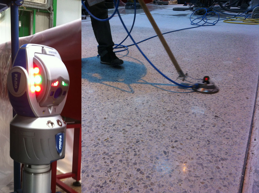
For the most part this site is in French as I have deemed that the French market is the most in need of clarification regarding the various aspects of decorative concrete and specifically polished concrete. I will now break from that focus in order to potentially reach a specifique audience. This page will take an indepth look at floor flatness and the topic will be treated in English. My experience on this subject comes from several projects, but one in particular I was asked to do in 2014. The company I was a partner in was contacted by the CEA in Paris. The CEA (Centre d'etude atomique) is part of the national French research institution, the CNRS (Centre Nationale de Recherche Scientifique). This is France's top scientifique organization and they are in the forefront of many branches of scientific development. The CEA at Saclay (just outside of Paris) is a nuclear research facility with a proton reactor dedicated to research projects. The principal use of the reactor is proton scanning. This provides an atomic level view of the matter and elements scanned. The reactor is attached to a large hangar with a grouping of scanning "stations". These are the blocks that receive the neutrons permitted to stream out of the reactor. Each scanning station is equipped with an extremely flat floor. The flat floors support special disks on which the capturing equipment sits. These disks are metal, about 15 centimeters in diameter and contain vent-holes on the underside that allow pressurized air to create an air cushion between the plate and the floor. This cushion of air allows the equipment to float on the floor which means it can be moved by one person and small position adjustments can be made easily. After the pressurized air is cut and the equipment descends the half millimeter to rest again on the floor. This system requires an extremely flat floor. In the past the CEA used synthetic marble slabs 50 cm by 50 cm, cemented in place by a very talented "marbrier", an old guy who really knew his work. Two factors made their flat floor demands take a new direction: The "marbrier" reached the age of retirement and there was no one with his skill level to replace him. The other factor was they wanted to explore a more economical solution. So the CEA management asked if the same level of flatness couldn't be acheived with the techniques of concrete polishing. We got their call in the Spring of 2014. We admitted immediately that we had no idea if polished concrete could attain the same level of flatness as their computer machined marble slabs. But we were okay to give it a go. The name of the proposed floor was Eros.
Constraints of Eros

Grinding and Mesuring
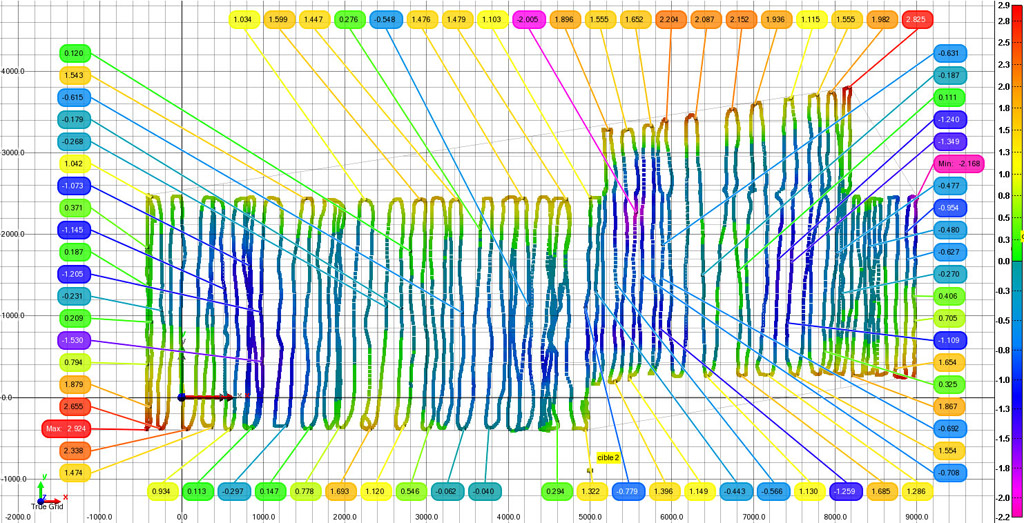
We identified from the very begining of the grinding process that "data" regarding the state of the floor was crucial. We couldn't proceed if we didn't know where we were. It is critical to understand that a grinding machine is only as smart as it's operator and there is absolutely no way of telling what exactly the grinder is doing. This can be a problem on a classic polished concrete job, for us it was paramount. I demanded from the team at the CEA outputs on paper of the floor scans. I wanted a visual representation of what was happening on the floor. Unfortunately, the Faro software was unable to provide a cartographic representation of the surface with contour lines. At the beginning, all we had were pinpoint data indicating the Z height at the points where the data was taken. Our maps looked like this, and I had difficulty visualizing the relationship between one area of the floor and another.

So I requested that the scans be provided as x,y, and z data only. These points I then ran through special software that output a true contour map. I set the divisions between the lines to 1/10th of a millimeter. As such I knew that once I reached a distance of 10 centimeters between each line I was in spec.
Machine aspects

Up to this point I have simplified and jumped over quite a few things that actually happened during the job. This is intentional, for as we did make quite a number of very important mistakes, each mistake was in the end very revealing as to what exactly is going on underneath a rotary-head grinding machine. What a modern surface grinder is actually doing remains a near-total mystery, and even amonst the guys and gals manufacturing these machines. It is for this reason that (to my knowledge) there doesn't exist a comprehensive grinding system that can consistently produce highly-flat floors like what we eventually acheived at the CEA. The reasons for the difficulty in acheiving highly flat floors are multiple and interconnected.
Z measurement

The first problem you have is a diamond tool underneath the machine that is "wearing" in the opposite direction to the floor. This is why a laser on the machine is always problematic. If you put a laser on the machine for the z measure, it is constantly getting more and more off as the diamonds wear down underneath the machine. We discussed at length a possible process of recalibrating the z of the diamond tools on a regular basis, but this solution had its own problems. As well it was useless when the machine was in motion as there was too much vibration of the machine for precision z messurements.
Concrete hardness

Another problem often overlooked is that floor hardness is not consistent across the entire area of the floor. It changes from zone to zone and point to point. An increase in granulats will make an area harder than a little farther on where there are less rocks. This might seem negligable, but it is not. The harder the floor, the less the diamonds attack the surface. This results in a variation of descent into the matter that is not consistent over the area being treated. This will actually throw the floor out of flatness, and can make the floor less flat as opposed to more flat.
Machine weight, pressure on the surface

Like the HTC All system, a very important element of grinding is weight of the machine which translates into pressure on the surface. It is for this reason that, in general, the larger the machine, the more aggressive the machine. "It goes down faster" as a grinder would say. And this is true. However what is overlooked is that the pressure is not consistent across the surface of the head of the machine. This is because the floor itself is not flat. The higher the floor, the higher the pressure. This wouldn't seem to be a problem, and this is what in actuality causes the "natural" flattening of a ground and polished floor. That is to say that high points on the floor get increased pressure, thus the machine is more aggressive on these points than surrounding points. All is well until we take into account two other elements: turning, and machine-head pivot. First, when a machine gets to the wall it has to turn. This means that due to centrifugal force the weight of the machine tips in one direction or another. This additional force is capable of creating significant increase in "attack" of the grinding tools. For proof, go back up to the image 'Contour map'. Have a look at the blue area all the way to the right. This was a three-centimeter depression created by the machine itself in under three minutes and was entirely due to operator manipulation (me) in right and left turning in a small zone. This "error" ended up costing the project over 10 grand ( in Euros).
The second element is machine-head pivot. Most manufacturers are totally unaware of the implications of this. There are two types of pivot amongst machines, either x-pivot only(like early generation HTC machines), or x,y-pivot (like Lavina machines, amonst others). The argumentation for the difference is that the manufacturers claim that an x,y-pivot will give you a flatter floor. Also the head of the machine will be better able to "get into" low spots so as to "grind better" by "touching more". This is not false, but it hides a critical fact when it comes to the aspects of grinding flat. The true result of this pivot is that for every action, there is a re-action. That is to say that as the machine comes to a bump, the front of the head starts to climb the little hill and pressure is increased at this point. However, as one would expect but perhaps not think too much about, as the front pivots up, the back pushes down, so you have a nearly equal pressure being applied to the rear of the grinding head. As we scrape off the top of the hill we are at the same time digging a hole at its base. And it is now important to take into the calculation the fact that the machine is moving forward. But before we get there, remember, going uphill creates more pressure, and going downhill, less pressure. This dynamic dictates that in fact it is the existant absence of flatness of the floor that is guiding the machine. The machine is at the mercy of the floor itself as a guide, and in the long run will do minimale alteration. To a far greater extent the grinding process will simply "attenuate" the floor, but can never get near a high level of flatness because as it is is correcting in one sense, it is "de-correcting" in exactly the opposite manner on the opposite side.
Foward movement

But not all is lost. Todays machines ARE flattening floors. And this is due to the overall generalized forward movement of the machine. As the machine "tops" the hill, all the pressure is concentrated on the high point of the hill. This results in a net decrease in general to high points on a floor. And results in general flattening properties overall.
Conclusion
But without a comprehensive understading of how the dynamics of grinding heads operate on an unlevel surface, high-level flatness is impossible with classic methods. With a lot of time and many modifications to the overall system, the floor Eros at the CEA Saclay in Paris became (to my knowledge) the flattest open-traffic concrete floor in the world. <1/10th of a millimeter variation over 100 millimeters. 90% of the suface is within spec, with only peripheral border zones not reaching the same level of flatness.
We developed mechanical systems that aided us as well as therorical systems that could make the process commonplace.
If you are interested in this subject don't hesitate to contact me, and thanks for reading!